


You’re designing a solar array—rooftop, ground-mount, or carport. The DC side needs reliable connections between modules, combiners, and inverters. A solar harness does exactly that: it’s a pre-assembled branch connector that simplifies wiring, reduces installation time, and ensures consistent, weatherproof connections across the array. The SH-X Branch is one example—a compact branch solution rated for 1500V DC, capable of handling up to 50A, with IP68 waterproofing and UV resistance built in. This guide covers what these harnesses do, what specifications matter, and how to choose the right branch connector for your photovoltaic system.
What a Solar Harness Does in a PV Array
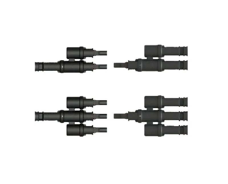
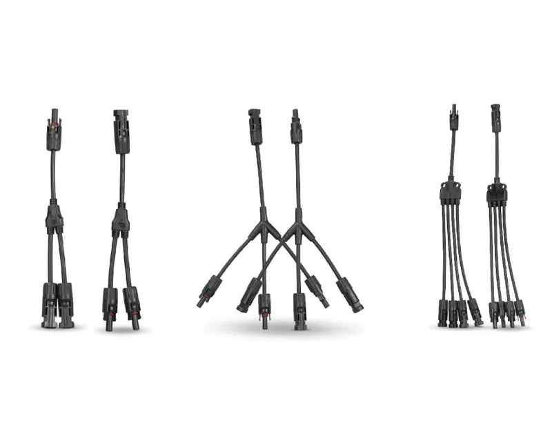
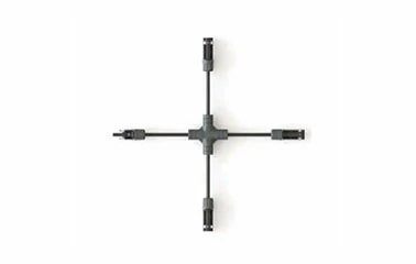
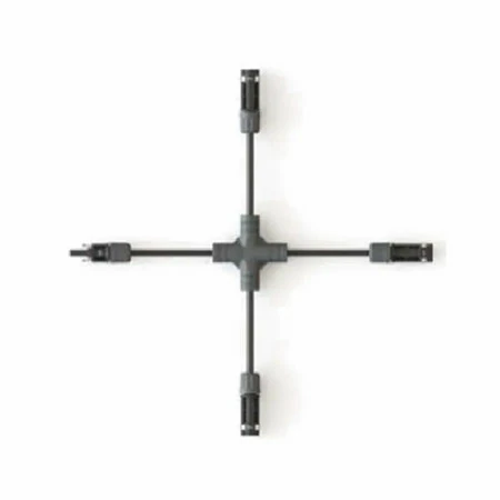
A solar harness is a branch connector that allows multiple PV strings to be combined or distributed within a solar array. It eliminates the need for field-wired splices, reducing both installation time and the potential for wiring errors. The SH-X Branch, for example, provides a reliable junction point for cables ranging from 4mm² to 16mm², supporting both series and parallel string configurations. By using pre-assembled harnesses, installers can achieve consistent, repeatable connections across large arrays.
Branching vs. Tapping
In a typical PV array, multiple strings need to be combined at combiner boxes or inverters. A branch harness provides a clean, organized way to make these junctions without the mess of field-spliced wires.
Pre-Assembled Reliability
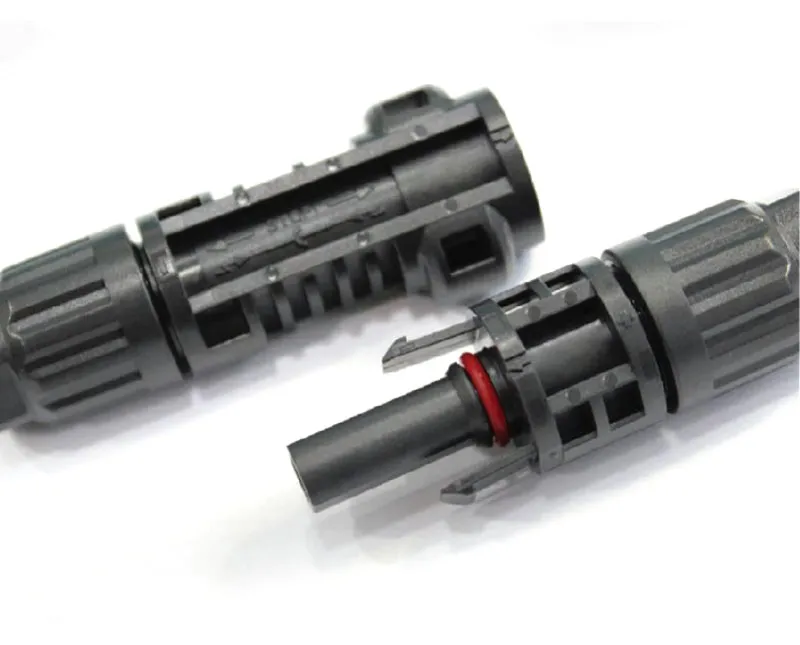
Pre-assembled harnesses are built in controlled factory conditions, ensuring consistent crimp quality and sealing. This reduces the risk of field installation errors—loose connections, improper torque, or inadequate sealing—that can lead to hotspots, power loss, or fire hazards.
Voltage and Current Ratings — Matching the Harness to Your System
Solar systems are trending toward higher voltages. The SH-X Branch is rated for DC 1500V maximum system voltage, with a maximum rated current of 50A. This makes it suitable for modern high-voltage solar arrays—both commercial and utility-scale. For lower-voltage systems, the same harness provides headroom for future upgrades.
Why 1500V Matters
Higher system voltage allows longer string lengths, reducing the number of combiner boxes and lowering overall system cost.
Current Capacity and Cable Compatibility
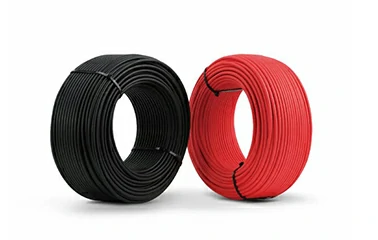
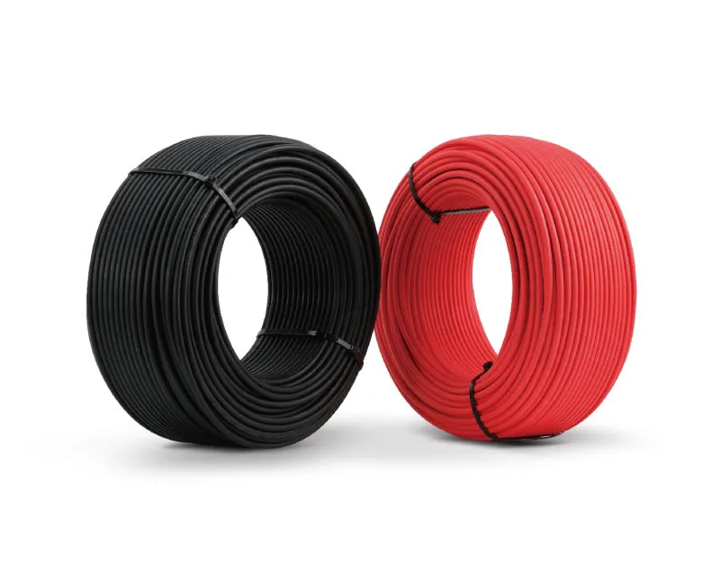
The SH-X Branch accepts cables from 4mm² to 16mm², providing flexibility to match different string currents and voltage drop requirements.
Environmental Protection — IP68 and UV Resistance
Outdoor solar installations face harsh conditions: rain, humidity, UV radiation, and extreme temperatures. The SH-X Branch is rated IP68—the highest waterproof rating for electrical connectors—meaning it can withstand continuous immersion in water. It also features UV-resistant materials that prevent degradation from prolonged sunlight exposure.
IP68 in Practice
IP68 means the harness can be submerged in water beyond 1 meter for extended periods. In solar installations, this translates to reliable performance in heavy rain, snowmelt, or even temporary flooding.
UV Resistance for Long-Term Outdoor Use
UV radiation degrades many plastics over time, leading to cracking and loss of sealing. The SH-X Branch’s UV-resistant materials maintain their integrity over the 25+ year lifespan of a typical solar array.
Wide Temperature Range
The harness operates in temperatures from -40°C to 85°C, covering everything from desert heat to arctic cold. This wide range ensures reliable performance across diverse climates and seasons.
Certifications That Matter
Solar components must meet rigorous safety and performance standards. The SH-X Branch has passed both IEC1500V and UL1500V certifications, with qualification testing performed in TUV and ETL labs. For solar projects requiring insurance approval or regulatory compliance, these certifications provide the necessary documentation.
IEC vs. UL Standards
IEC 1500V certification confirms compliance with international electrotechnical standards, widely accepted in Europe and other regions. UL1500V certification is the equivalent North American standard, required for projects in the US and Canada.
TUV and ETL Lab Qualification
Qualification in TUV and ETL labs means the harness has been independently tested to meet solar professional standards.
| Specification | SH-X Branch | Why It Matters |
|---|---|---|
| Rated voltage | DC 1500V | Suits modern high-voltage solar arrays |
| Rated current | 50A | Covers most string applications |
| Cable range | 4mm² – 16mm² | Flexible cable compatibility |
| Waterproof rating | IP68 | Protects against immersion and heavy rain |
| UV resistance | Yes | Prevents material degradation from sunlight |
| Temperature range | -40°C to 85°C | Performs in extreme climates |
| Certifications | IEC1500V, UL1500V | Meets international and North American standards |
| Test labs | TUV, ETL | Independent qualification |
Key Features That Ensure Long-Term Reliability
Beyond the basic specifications, several features contribute to the harness’s long-term performance. Lower contact resistance and higher current transfer capability ensure high product efficiency. The use of high-quality materials guarantees long-term reliability.
Low Contact Resistance
Low contact resistance minimizes power loss at the connection point, improving overall system efficiency.
Halogen-Free Materials
The harness uses halogen-free materials, reducing toxic smoke emission in the event of a fire.
Heavy Metal Compliance
Material content is controlled to limit lead, cadmium, and other heavy metals, meeting environmental and regulatory requirements.
What Installers Ask About Solar Branch Connectors
What is the maximum voltage and current for the SH-X Branch?
The SH-X Branch is rated for DC 1500V maximum system voltage and 50A maximum current.
What cable sizes does it accept?
It accepts cables from 4mm² to 16mm², providing flexibility for different string configurations.
Is it waterproof?
Yes. The SH-X Branch has an IP68 waterproof rating, meaning it can withstand continuous immersion in water. It also features UV-resistant materials for long-term outdoor use.
What certifications does it have?
The harness has passed both IEC1500V and UL1500V certifications, with qualification testing performed in TUV and ETL labs.
How does it perform in extreme temperatures?
It operates from -40°C to 85°C, covering desert heat, arctic cold, and everything in between.
Get the Right Solar Harness for Your Array
Selecting a solar branch harness comes down to three factors: voltage rating (match your system), current capacity (match your strings), and environmental protection (match your site conditions). Request a quote or sample → —Suntree‘s team can help you select the right SH-X Branch configuration for your specific array layout and cable requirements.
This article was written with the assistance of AI to organise technical data from Suntree’s product documentation and industry standards.
Suntree has nearly 20 years of experience in the solar cable industry, with a technical R&D team of over 50 people and a matching database of more than 500 projects covering all typical extreme environments worldwide. The SH-X Branch Solar Harness features a 1500V DC rating, 50A maximum current, IP68 waterproofing, UV resistance, and an operating temperature range of -40°C to 85°C. It is certified to IEC1500V and UL1500V standards with TUV and ETL lab qualification. Suntree provides full-process quality control with halogen-free materials and strict heavy metal limits. Connect with Suntree to discuss your system voltage, cable specifications, and project requirements.
-1327.webp)


