You‘ve seen it on site. A string of panels tests fine at commissioning. Six months later, the thermal camera shows a hot spot at a connector. Another six months, and that connector has failed—arcing, melted plastic, a string down. The root cause? Almost always the installation. A conductor strand nicked during stripping. A crimp that wasn’t fully compressed. A gland nut left half a turn loose.
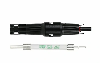
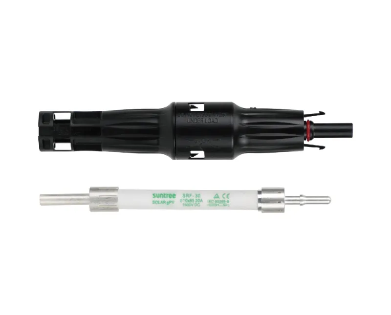
Here‘s the reality: a solar connector is only as reliable as the person who installs it. The Suntree PMCN40-CM is a rugged, UV-resistant MC4-style connector rated for DC 1500V and up to 40A, with IP67 protection when mated. But even the best connector fails if the installation is wrong. This guide walks through the complete installation sequence—from tools and cable preparation to crimping, assembly, and verification—so your connections stay reliable for the life of the array.
Tools and parts — don‘t start without these
Good installation starts with the right tools. Using the wrong crimper or a worn blade guarantees a poor connection.
What’s in the tool bag
-
MC4 crimping tool – A ratcheting crimper with hexagonal dies, capable of 1,500–2,000 lbs of force. Do not use a generic electrical crimper—the die profile is wrong for MC4 contacts.
-
Wire stripper – Designed for solar PV cable, with precise depth control to avoid nicking strands.
-
Multimeter – For continuity and contact resistance checks.
-
Torque wrench or torque screwdriver – For the gland nut (target: 3.4 Nm).
What you‘ll need on site
-
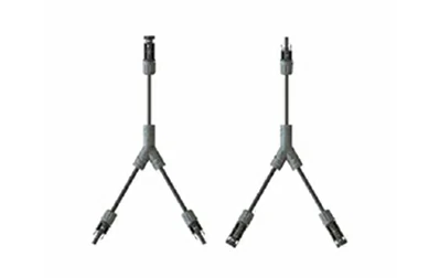
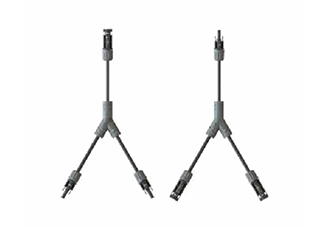
Suntree PMCN40-CM connector pair – Includes male and female housings, crimp contacts, sealing rings, and cable glands.
-
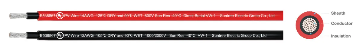
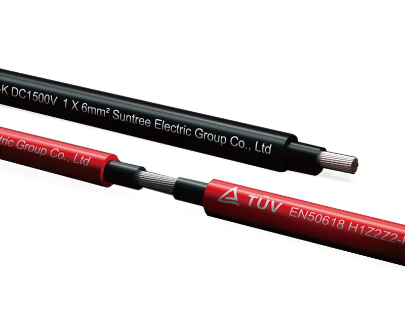
Solar PV cable – 2.5–10mm² (14–8 AWG), rated for 1500V DC.
-
Cable ties – For strain relief and cable management.
Get the cable ready — the right way
Cable preparation is where most installation errors begin. A nick in the conductor or a stray strand can create a hot spot that fails years later.
Strip it clean — no nicks
Strip 10–12mm of insulation from the cable end, depending on the connector brand. For Suntree PMCN connectors, the exact strip length is specified on the connector packaging. Use a wire stripper with the correct gauge setting—never a knife. A knife cut can score the copper strands, creating a weak point that breaks under vibration.
Three things to look for before you crimp
-
No nicked or cut strands – Hold the stripped end up to light. Any broken strands indicate a poor strip.
-
No oxidation – Copper should be bright and clean. If it‘s dark or greenish, cut back to fresh conductor.
-
Twist the strands – Gently twist the conductor strands together to keep them uniform before inserting into the crimp contact.
The crimp — one shot is all you get
The crimp is the single most critical step. A poor crimp creates resistance, and resistance creates heat.
Get the wire in the barrel — all the way
Insert the stripped cable end into the metal crimp contact. The conductor should extend slightly past the crimp barrel—you should see a small amount of copper visible beyond the barrel. If it‘s too short, the crimp won’t grip the full length of the conductor. If it‘s too long, strands may protrude and cause shorts.
One crimp. That’s it.
Place the contact in the correct die position of the ratcheting crimper. Squeeze until the ratchet releases—this ensures full crimp force has been applied. Do not crimp twice. Double-crimping work-hardens the copper and can create stress fractures.
Look at it before you move on
A good crimp shows:
-
The crimp barrel is fully closed, with no gaps
-
No sharp edges or burrs
-
The conductor is visible at the end of the barrel but not protruding excessively
Give it a yank
Give the cable a firm pull—it should not separate from the contact. The industry standard pull test for MC4 crimps is 310 N minimum. If you can pull the contact off with moderate force, the crimp is unacceptable.
Putting it together — in the right order
With the contact crimped, the rest of the assembly is mechanical—but still requires attention to detail.
Don’t forget the seal
Before inserting the contact into the housing, slide the cable gland and the sealing ring onto the cable. The order matters: gland first, then seal. If you forget either, you‘ll have to cut the crimp and start over.
Push until it clicks
Push the crimped contact into the connector housing until you hear a distinct click. The contact is fully seated when it locks into place and cannot be pulled back out. For the PMCN series, the snap-in locking system is designed for secure engagement.
Tighten it right — not too much, not too little
Slide the cable gland forward and thread it onto the connector housing. Hand-tighten first, then add 1/4 turn with a torque wrench. The recommended torque for MC4-style connector gland nuts is 3.4 Nm. Over-tightening can damage the seal; under-tightening allows moisture ingress.
Prove it works before you walk away
A connector that passes visual inspection can still fail electrically. These checks catch problems before they become field failures.
Does the signal get through?
Use a multimeter to verify continuity from the exposed conductor at one end of the cable to the contact pin at the other end. No continuity means the crimp didn‘t make contact.
Measure the resistance — catch a bad crimp
For a more thorough test, measure the resistance across the crimped connection. The PMCN series specifies contact resistance of <0.35 mΩ. Higher resistance indicates a poor crimp.
Look for gaps
Inspect the assembled connector for:
-
No gaps between the gland and the cable jacket
-
The sealing ring is seated and not pinched
-
The housing halves are fully mated with no visible gap
Three problems installers run into
Q: No click? Something‘s not seated
If the male and female connectors don‘t snap together with an audible click, the contacts aren’t fully seated. This usually means the crimped contact wasn‘t pushed all the way into the housing. Remove the contact (using the release tool), reinsert it fully, and try again. A connector that isn’t fully mated has higher contact resistance and is vulnerable to water ingress.
Q: Squished too much or not enough — how to spot it
Under-crimped contacts show visible gaps in the crimp barrel—you can see light through the seam. They also fail the pull test easily. Over-crimped contacts show stress fractures or cracking at the crimp edges, or the conductor strands may be crushed and splayed. The correct crimp has a smooth, closed barrel with no gaps and no fractures. Suntree PMCN contacts are designed for use with standard MC4 crimping tools; using the correct die is essential.
Q: Reuse the connector? Better not
Generally, no. Once a crimp contact has been inserted and then removed, the locking tang is often deformed. The seal may also be compromised. For a reliable installation, use a new connector if you need to redo the assembly. The cost of a new connector is far less than the cost of a field failure.
Your final sign‑off list
Before you close out a string or a combiner box, run through this checklist:
-
Cable stripped to correct length (10–12mm)
-
No nicked or cut conductor strands
-
Crimp made in one stroke with ratcheting tool
-
Crimp barrel fully closed, no gaps
-
Pull test passed (310 N minimum)
-
Contact inserted until click heard
-
Gland nut torqued to 3.4 Nm
-
Male and female connectors mate with audible click
-
Continuity verified with multimeter
How Suntree‘s PMCN series supports reliable installation
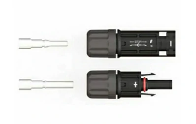
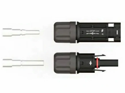
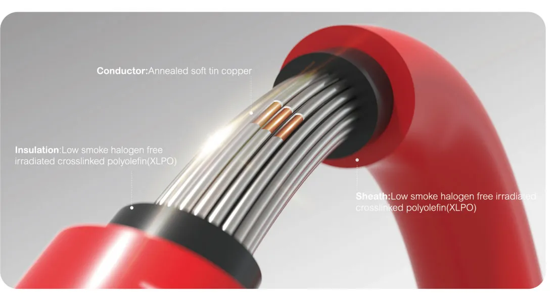
Suntree’s PMCN40-CM is an MC4-style solar connector designed for professional PV installations. Rated for DC 1500V with current capacity up to approximately 40A, it suits 2.5–10mm² (14–8 AWG) solar cables. The connector uses crimped copper, tin-plated contacts for low contact resistance (<0.35 mΩ) and snap-in locking housings that provide a secure mechanical and electrical connection. When mated, the IP67 rating delivers dependable performance in harsh outdoor environments.
The connector body is made from PPE/PC/PPO insulation material with a temperature range of –40°C to +85°C, covering extreme environmental conditions. The UV-resistant housing maintains its mechanical properties even after years of direct sunlight exposure.
For installation crews, the PMCN series is designed for simple on-site processing with standard photovoltaic crimping tools. The keyed housings ensure correct polarity mating, reducing the risk of reverse connections.
Before you install your next string of connectors, take five minutes to review this guide with your crew. One poorly installed connector can take down an entire string—and the cost of that downtime far exceeds the cost of getting the installation right the first time.
Need MC4 connectors or installation support for your next solar project? Contact Suntree for a quote on the PMCN series 1500V DC PV connectors. Share your cable gauge (2.5–10mm²), required quantity, and project voltage—their team can provide product specifications and installation guidance for your site.