That burned smell from the combiner box? In many cases, a solar connector was the starting point.


You walk a solar site after a hot spell. Output is down on a string. You open the combiner box – faint burnt smell, discolored plastic, melt marks around a branch connection. A solar connector might seem like a minor part, but field data shows it accounts for nearly one in five system failures. According to a TÜV Rheinland global PV failure analysis, connector-related issues make up 19.7% of all faults – second only to inverter problems at 34.2%. This article breaks down what causes those failures, what the specifications on a solar connector datasheet actually mean for a project, and how series like A4 nB1 and PMCN address heat, moisture ingress, and contact resistance drift
The quiet killer: contact resistance creeping upward
When you specify a PV system, you check panel wattage and inverter efficiency. The connectors at every junction are often an afterthought, yet a large solar farm can contain tens of thousands of connection points. The most frequent failure mechanism is not mechanical breakage. It is a slow, invisible increase in contact resistance. As that resistance rises, the connection generates more heat under load. The heat accelerates oxidation on the contact surfaces, which further increases resistance. This cycle continues until the plastic housing softens or the metal contacts arc.
TÜV Rheinland’s failure breakdown lists contact resistance increase as 42% of documented connector faults. That is nearly half of all failures. The remaining issues split between seal failures (28%) and mechanical damage (18%). A solar connector that maintains contact resistance below 0.5mΩ, as required by IEC 62852 standards, will not enter this runaway heating cycle. Once resistance passes 0.5mΩ under load, the temperature at the mating interface can rise by tens of degrees within weeks, not years.
What IP68 actually buys you when the monsoon hits
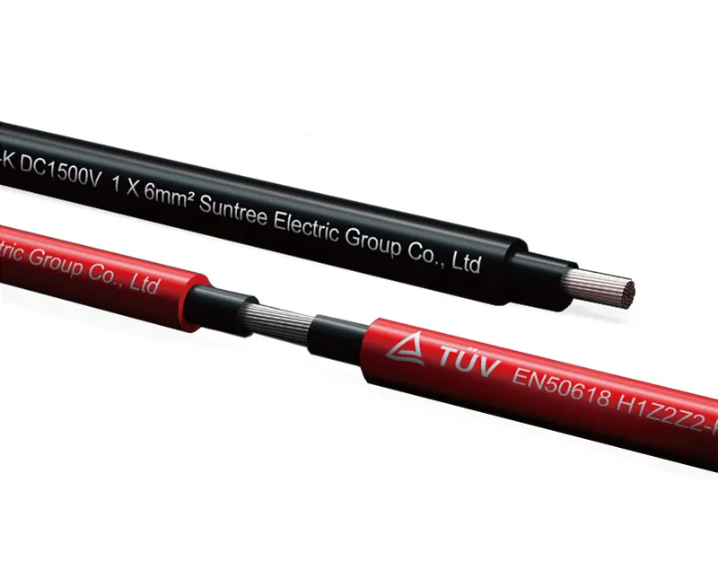
Outdoor connectors live a hard life. A connector under a panel on a flat commercial roof experiences temperature swings from freezing to overheating, UV exposure, and wind-driven rain. In coastal areas, salt-laden moisture seeps into any gap.
The datasheets list IP ratings. IP68 means dust‑tight and capable of submersion beyond 1 meter. That is not a marketing claim. On a real site, IP68 prevents the slow capillary ingress of moisture that eventually lowers insulation resistance to the point where tracking currents form across the plastic surfaces. Once tracking begins, the connector carbonizes and fails.
The PMCN series, for example, carries an IP68 rating and an operating range from -40°C to 125°C. Those numbers mean the seal compound remains flexible at low winter temperatures and does not soften or outgas at peak summer temperatures inside an unvented junction box.
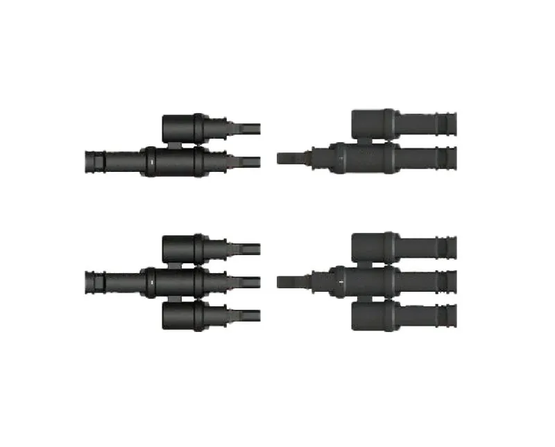
Branch connectors: where one string meets another
A standard PV branch connector, such as the A4 nB1 series, solves a specific layout problem: how to combine multiple strings into a single feed without creating a bulky, unsealed junction. The A4 nB1 connects two or more inputs into one output, using the same weather‑resistant materials found in inline connectors.
The A4 nB1 series branch connector carries a rated voltage of IEC 1500V DC and a rated current of 70A. That current level suits modern high‑wattage panels and large‑format strings. The design eliminates exposed copper and field‑made splices, which are a common source of corrosion in older systems.
Key parameters for the A4 nB1 series branch connector and related series are shown below:
| Series / Model | Rated Voltage | Rated Current | IP Rating | Temperature Range |
|---|---|---|---|---|
| A4 nB1 Branch | IEC 1500V DC | 70A | IP68 (typical) | -40°C to 125°C |
| PMCN Series | 1500V DC | 40A (stamped) / 70A (lathed) | IP68 | -40°C to 125°C |
| PMCN Plus | IEC 1500V & UL1500V | 120A | IP68 | -40°C to 125°C |
| PMBC n‑to‑1 | 1000V DC (IEC) | 30A | IP68 | -40°C to 75°C / 90°C |
Material selection: where the 25‑year design life actually lives
A solar plant is expected to operate for 25 years. The panels degrade slowly. The aluminum frames corrode but stay functional. The connector, however, is a mechanical and electrical interface that sees thermal cycling every day. Plastic housings expand and contract. Metal springs lose tension.
Most reputable manufacturers use PPO (polyphenylene oxide) or similar high‑temperature engineering plastics for the housing. PPO provides good dimensional stability, flame retardancy, and UV resistance. It does not become brittle after years of sunlight exposure. Suntree specifies halogen‑free materials and controls heavy metal content such as lead and cadmium across its production chain. This matters for end‑of‑life recycling, but also for reducing electrochemical corrosion inside the connector under wet conditions.
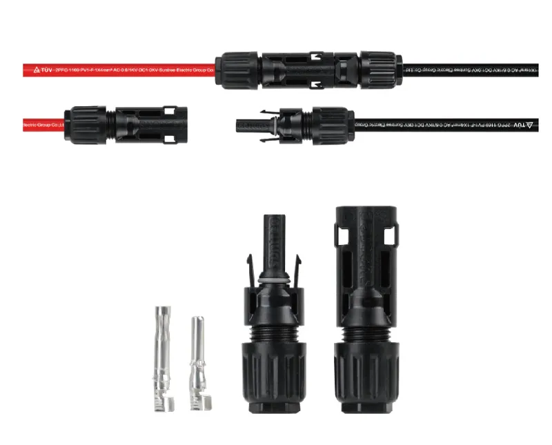
Current ratings: stamped vs. lathed pins
Open a PV connector datasheet, and you will see two current numbers for the same basic housing. The PMCN series, for instance, lists 40A for a stamped pin version and 70A for a lathed (machined) pin version.
A stamped pin is formed from flat sheet metal. It is cheaper to produce in high volume, but the contact surfaces are less precisely controlled. A lathed pin is machined from solid bar stock. It has a smoother surface, more uniform cross‑section, and typically lower and more stable contact resistance under load.
For high‑current strings, particularly those feeding into an inverter with MPPT inputs expecting full panel output even at noon, the lathed pin version pays for itself by reducing energy lost as heat at every connection.
Cross‑mating: the rule you cannot break
One of the most common field errors is mixing connectors from different manufacturers, even when they appear mechanically compatible. A male MC4‑style connector from Brand X plugged into a female MC4‑style connector from Brand Y. They click together. They seem fine.
But the qualification standards for PV connectors, IEC 62852 and UL 6703, explicitly test only same‑type or same‑family connectors from a single manufacturer. Cross‑mating invalidates the safety certification. The contact geometry, spring force, and sealing dimensions differ in ways that are not visible without destructive testing.
The practical risk is a connection that passes an initial resistance check but develops high localized heating after a few months of thermal cycling. That heating leads to the failure path described earlier: higher resistance, more heat, eventual meltdown.
What a connector datasheet should tell you before you order
When evaluating a new solar connector for a project, ask for five specific numbers:
-
Contact resistance – Should be ≤0.5mΩ for a new, unmated connector. Lower is better (0.2–0.3mΩ is typical for premium lathed‑pin designs).
-
Contact material and plating – Tin plating is common, but silver‑plated or gold‑flashed contacts resist oxidation better in humid or corrosive environments.
-
Sealing type and IP rating – IP68 is standard for field‑installed PV connectors. Check that the test duration and depth (e.g., 24 hours at 1 meter) match your site conditions.
-
Rated current vs. actual string current – A 40A rating is sufficient for many residential strings. Commercial strings with large‑format panels may exceed 40A, requiring a 70A or 120A rated model.
-
Third‑party certification – Look for IEC 62852 and, for North American projects, UL 6703. These are not optional. Some manufacturers list “pending” certification; for a commercial installation, pending is not acceptable.
Choosing between inline and branch connectors
Most of a solar plant uses inline connectors – male and female pairs that link one panel to the next. Branch connectors are different. They combine multiple input strings into one output cable, which then runs to the combiner box or inverter.
Inline connectors are specified by current and voltage. Branch connectors must also handle the mechanical support of multiple cables entering a single body. The A4 nB1 series branch connector is designed for mid‑string combining where the total current does not exceed 70A and the system voltage stays within 1500V DC.
If your layout requires combining more than two strings into one output, a series like PMBC with multiple input ports may be a better fit. The PMBC series n‑to‑1 connector rated at 30A and 1000V DC suits lower‑current combining, such as matching smaller panel strings.
Warranty, supplier history, and what they usually hide
A connector might cost fifty cents more than a no‑name alternative. On a 5MW project, that difference across 5,000 connectors becomes $2,500. It is easy to cut that cost.
But consider the cost of a single failed connector on a commercial roof. The lost generation during diagnosis and repair, the labor to locate and replace the faulty connection, and the risk of fire liability make that $2,500 saving small.
Sellers who hide behind generic datasheets often have inconsistent supply quality. A reliable solar connector supplier documents its material traceability, publishes test reports for each production batch, and offers a real warranty.
Suntree maintains a full‑process quality control system and a digital traceability database allowing real‑time access to supply chain data. The company provides a warranty period of 24 months on some product lines, together with ISO 9001, 14001, 45001, and even ISO 27001 for information security management. For a major project, knowing that the supplier holds those certifications indicates a level of process maturity that usually extends to production quality as well.
Sizing connectors for the next‑generation 1500V architecture
The shift from 1000V DC to 1500V DC systems has been one of the major efficiency gains in utility solar. Higher voltage means longer strings, fewer combiner boxes, and lower balance‑of‑system costs.
Connectors for 1500V systems require thicker insulation, longer creepage distances, and higher‑grade plastics. The PMCN series is rated for 1500V DC, the same as the A4 nB1 series branch connector.
A solar connector certified only to 1000V DC must not be used in a 1500V string, even if the current is within its rating. The dielectric breakdown risk becomes unacceptably high, particularly in wet or high‑altitude conditions.
One thing you can verify without any test equipment
When connectors arrive on site, before installation, do an unplug‑replug check on a sample. A good connector makes a clean click. The insertion force should be firm but not excessive. The two halves should separate with a definite release, not a sticky pull.
If the connector feels gritty, does not fully seat, or separates too easily, reject that batch. These tactile symptoms often indicate poor molding tolerances or incompatible cable seal sizing. Field experience shows that connectors with poor initial fit almost always develop high contact resistance after a few thermal seasons.
Making the decision for your next string
A solar connector appears on every bill of materials, yet it rarely gets the scrutiny it deserves. The difference between a marginal connector and a well‑specified one is not just in the per‑unit cost. It is in the risk of a midday shutdown, a tracking current in a combiner box, or a call from the client about a strange smell on the roof.
The A4 nB1 series branch connector, the PMCN family, and the PMBC n‑to‑1 connectors illustrate the range of available options: different currents, different voltage ratings, all with IP68 sealing and high‑temperature materials. The right choice depends on your specific layout and local environmental conditions.
If you want to check the exact current rating for a particular cable size or confirm the certification status for a specific region, the surest route is to request the latest production batch datasheet directly.