How to Troubleshoot Low Power Output from Solar String Due to Wiring Issues


You're monitoring your solar array's performance, and one string consistently underperforms its neighbors. The panels are clean. No shading. The inverter shows no obvious faults. Yet the string is producing 15-20% less power than the others. The problem isn't the panels — it's the wiring.
The solar wire/cable connecting your panels to the inverter is often the overlooked culprit in underperforming strings. High resistance from poor connections, damaged insulation, or undersized cable can rob you of generation without any visible sign of trouble. When a solar string produces low power and the modules themselves aren't the issue, wiring faults are the primary suspect. This guide walks through how to recognize the symptoms, pinpoint the fault, and fix it — whether you're a maintenance technician or a plant manager.
Symptoms that point to wiring problems
Before you start chasing faults, know what you're looking for. Three symptom patterns indicate wiring-related power loss.
Normal voltage, low current
If the string's open-circuit voltage is close to normal but the operating current is significantly low, the issue is likely high resistance in the circuit. The resistance is dropping voltage under load, but the panels themselves are still generating adequate voltage.
Both voltage and current are low
When both voltage and current are low, the problem could be a partial short circuit, a ground fault, or severe resistance at a single connection point. This pattern often points to a connector that hasn't been fully seated or a cable with damaged insulation.
Inverter reports low insulation resistance
Modern inverters monitor insulation resistance to ground. If the inverter reports an insulation fault (typically below 1 MΩ), you have a cable insulation issue — either damaged insulation or moisture ingress. This is a safety hazard that needs immediate attention.
One string consistently underperforms compared to others
When one string in an array produces noticeably less than adjacent strings with the same orientation and tilt, the wiring is the most likely variable. Panels degrade uniformly; wiring faults are localized.
First step — measure string voltage and current
Start at the combiner box or inverter inputs. You need baseline measurements before you start disconnecting anything.
Tools you'll need
-
Digital multimeter (capable of DC voltage and current up to 1000V)
-
Clamp meter (DC current)
-
IR thermometer (for finding hot spots later)
-
MC4 connector release tool
What to measure
Measure the open-circuit voltage (Voc) and short-circuit current (Isc) of the suspect string. Compare these values to the design specifications for your array and to the measurements of neighboring strings. A deviation of more than 5% from expected values warrants deeper investigation.
Record these values for each string:
-
Voc (open-circuit voltage)
-
Isc (short-circuit current)
-
Operating voltage under load (Vmp)
-
Operating current under load (Imp)
Compare to neighboring strings
If the suspect string's voltage is 10% lower than adjacent strings but the current is similar, you likely have a partial short or a bypass diode issue. If the current is 10% lower but voltage is normal, you have high resistance in the circuit — a connection or cable problem.
Pinpointing high resistance in the circuit
Once you've confirmed the string is underperforming, the next step is finding where the resistance is.
Measure voltage drop across each connection
With the string under load (connected to the inverter), use a multimeter to measure voltage drop across each connection point — from the panel junction box to the MC4 connector, from the connector to the string cable, and at the combiner box terminals. A voltage drop of more than 0.5V across a single connection indicates excessive resistance.
Check positive-to-ground and negative-to-ground voltage balance
Measure the voltage between PV+ and ground, and between PV- and ground. In a properly functioning system with no ground faults, these voltages should be roughly balanced. A significant imbalance (more than 20% difference) indicates a ground fault or partial short to ground.
Measure circuit resistance with a small load
Disconnect the string from the inverter. Use a multimeter to measure the total resistance of the string circuit. Compare this to the expected resistance based on cable length and gauge. Excess resistance points to poor connections or damaged cable.
Isolate the fault by section
Start at the combiner box and work your way toward the panels. Measure resistance at each junction — first at the combiner box terminals, then at each string cable connector, then at each panel junction box. The section with the highest resistance contains the fault.
Common wiring faults found in the field
These are the five most common wiring issues that cause low power output in solar strings.
Connector not fully seated
MC4 connectors that aren't fully engaged create high resistance and can arc under load. The symptom: a hot connector (detectable with an IR thermometer) and a string that runs 10-20% below expected current. The fix: disconnect, inspect for damage, and re-engage until you hear a distinct click.
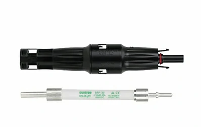
Damaged cable insulation
Cables can be damaged by rodents, landscaping equipment, or simple abrasion against racking. Damaged insulation creates a path to ground, reducing string current. The symptom: low current with normal voltage, and sometimes an insulation fault alarm from the inverter. The fix: cut out the damaged section and splice with an IP68-rated junction box, or replace the entire cable.
Loose terminals in the combiner box
Terminals that aren't torqued to specification create high resistance at the combiner box. The symptom: one string is underperforming, and the terminal feels warm to the touch. The fix: torque all terminals to the manufacturer's specified value.
Undersized cable for the run length
Long cable runs with undersized wire create excessive voltage drop. The symptom: the string voltage is consistently lower than expected, and the drop increases with current. The fix: calculate the voltage drop for your cable length and current, and upgrade to a larger gauge if the drop exceeds 3%.
Damaged connector pins
MC4 connector pins can become damaged during installation or from repeated mating cycles. Bent or corroded pins create high resistance. The symptom: intermittent low output that varies with weather. The fix: cut off the old connector and install a new one with a proper crimp.
How to fix each fault type
Once you've identified the fault, here's how to address it.
Loose or unseated connectors
Disconnect the connector, inspect the pins for damage or corrosion, and reconnect firmly. You should hear a positive click when the connector is fully seated. If the connector is damaged, replace it.
Damaged cable
If the damage is localized, cut out the damaged section and install an IP68-rated junction box to splice the cable. If the damage is extensive or the cable has been compromised along a long section, replace the entire cable run.
Loose terminals
Use a torque wrench to tighten all terminals in the combiner box to the manufacturer's specification. Do not overtighten — this can damage the terminal or the cable.
Undersized cable
Calculate the voltage drop for your cable run using the formula: Voltage Drop = (2 × Length × Current × Resistance per meter) / 1000. If the drop exceeds 3%, replace the cable with a larger gauge or add a parallel cable to reduce resistance.
Preventive inspection routine
A regular inspection program catches wiring issues before they cause power loss.
Weekly — infrared scanning of connection points
Use an IR thermometer or thermal camera to scan all connection points — MC4 connectors, combiner box terminals, and inverter inputs. A connection that is 10°C or more above ambient temperature is a sign of high resistance.
Quarterly — resistance spot checks on critical strings
Measure the resistance of a representative sample of strings. Track the results over time. A gradual increase in resistance indicates connector or cable degradation.
Annually — full string resistance measurement
Measure the resistance of every string in the array. Document the results. This baseline makes future troubleshooting much faster.
Maintain a fault code log
Document every wiring fault you find and the fix that resolved it. Over time, this log becomes a valuable reference for your team.
Questions technicians ask about solar wiring issues
Q: Can a single bad connector reduce the whole string's output?
A: Yes. A single connector with high resistance acts like a bottleneck in the circuit. The current through the entire string is limited by the highest resistance point. A connector with a 0.5V drop at 8A is wasting 4 watts of power — and the heat generated can accelerate connector degradation.
Q: What is an acceptable resistance for a 100m solar string?
A: For a 100m string of 4mm² PV cable, the expected resistance is approximately 0.9-1.0 ohms (round trip). If you measure significantly more than this — say, 1.5 ohms or higher — you have excess resistance from connections or damaged cable.
Q: Can a dirty connector cause power loss without visible damage?
A: Yes. Connector pins can develop a thin oxide layer from moisture ingress. This layer increases contact resistance without any visible corrosion. Clean the pins with a contact cleaner and re-seat the connector. If the problem persists, replace the connector.
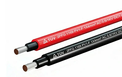
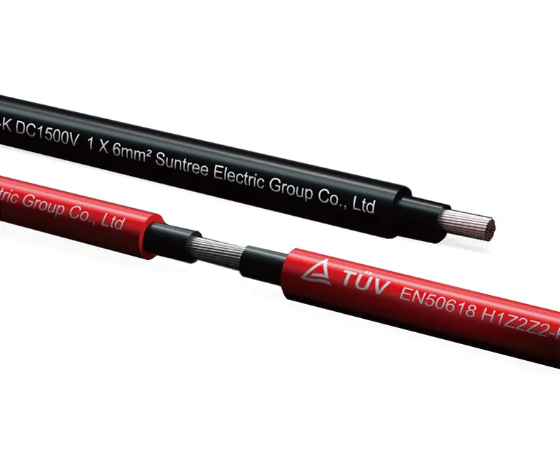
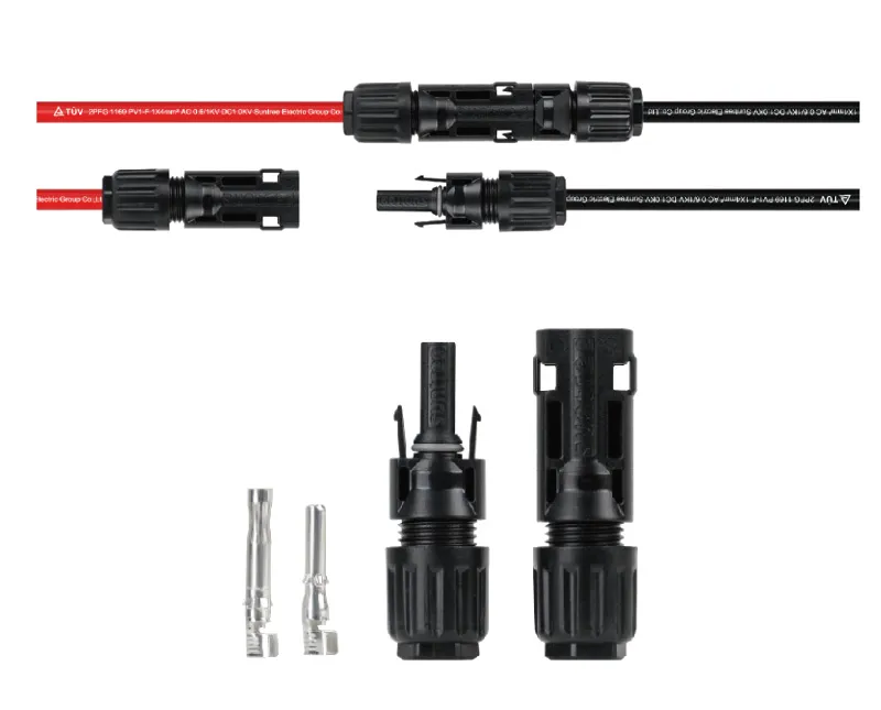
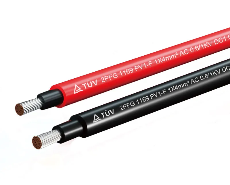
How Suntree's PV cable minimizes wiring issues
Suntree's TUV-certified photovoltaic cables are designed to reduce the wiring issues that cause power loss. The cables feature electron-beam cross-linked insulation, providing excellent resistance to UV, water, ozone, and abrasion. They are halogen-free, flame-retardant, and low-toxicity. The temperature range of -40°C to +120°C ensures reliable performance in extreme conditions. High flexibility and stripping performance make installation easier and reduce the risk of installation damage.
The cables are certified to TUV, CE, and UL standards, ensuring compliance with global safety and environmental regulations. For solar installations where wiring reliability is critical, the combination of high-quality materials and rigorous certification provides peace of mind.
Before you replace panels or inverters on an underperforming string, check the wiring. A loose connection, a damaged cable, or an undersized run is often the real culprit. With the right tools and a systematic approach, most wiring faults can be identified and fixed in under an hour.
Need help diagnosing a low-performing solar string? Contact Suntree for technical support or product consultation. Share your system configuration, string measurements, and fault symptoms — their team can help identify the root cause and recommend the right cable solution.