 English
 Deutsch
 Pусский
 Español
 Français
 Português
How to Properly Size Solar Cable for Commercial PV Systems


You‘ve sized the inverter, selected the modules, and laid out the array. The design looks solid until the Authority Having Jurisdiction sends back the permit set with a rejection notice: conductor ampacity insufficient for rooftop ambient conditions. An undersized Solar Cable doesn’t just fail inspection—it overheats, accelerates insulation breakdown, and can become a fire hazard. Oversizing by two gauges drives up material cost unnecessarily. The sweet spot is precise: enough ampacity after all derating, voltage drop low enough to avoid energy loss, and mechanical strength adequate for the installation.
Where the current calculation actually starts
The foundation of any conductor sizing is the circuit‘s maximum current. For PV source circuits, NEC 690.8(A) requires using the module’s short-circuit current (Isc), not its operating current (Imp). Isc is typically 5–10% higher than Imp on crystalline silicon modules.
From this base, apply a continuous current multiplier of 125%. This accounts for the fact that PV systems operate continuously for three hours or more, and conductors must be sized accordingly. As the name suggests, solar arrays receive high levels of sunlight, so conductor sizing should be based on the maximum current under worst-case irradiance.
But here‘s where designs fail: many stop after one multiplier. The correct sequence is:
-
Isc × 1.25 × 1.25 = 156% of Isc — the required ampacity before any derating is applied
The reason for the second 125% is baked into the NEC structure: 690.8(A) establishes the maximum circuit current (Isc × 1.25), and 690.8(B) requires the conductor’s ampacity to be at least 125% of that value. Together, they form the 156% rule.
Example. A module with Isc = 13A yields a maximum circuit current of 16.25A (13A × 1.25). The conductor must then have an ampacity of at least 20.3A (16.25A × 1.25) before any temperature or conduit corrections are applied. If the designer used Imp instead of Isc or applied only one multiplier, the system would pass desk review but likely fail field inspection.
Where the real challenge begins
The 156% number is the starting point. Environmental conditions and installation methods then reduce the conductor‘s effective ampacity. This is where most commercial PV designs fail. Account for both temperature correction and conductor bundling derating using the NEC 310.15 tables.
Temperature correction. Ambient temperatures on commercial rooftops can easily reach 45–55°C. For a conductor rated 90°C, a 45°C ambient applies a 0.87 correction factor, reducing effective ampacity by 13%. At 50°C, the factor drops to 0.82 — a full 18% reduction.
Conduit derating. When more than three current-carrying conductors share the same raceway, they heat each other and ampacity must be adjusted. Four to six conductors require a 0.80 factor; seven to nine require 0.70.
Combined effect. A conductor with 30A base ampacity, installed at 45°C ambient (0.87 factor) with seven conductors in a conduit (0.70 factor), has an effective ampacity of only 30A × 0.87 × 0.70 = 18.3A. If the 156% calculation required 20.3A, this conductor would be undersized by over 2A — enough to fail inspection.
| Installation Condition | Correction Factor | Combined Effect (30A Base) |
|---|---|---|
| 45°C ambient (90°C insulation) | 0.87 | 26.1A |
| + seven conductors in conduit | 0.70 | 18.3A |
| 50°C ambient + nine conductors | 0.82 × 0.70 = 0.57 | 17.1A |
| Rooftop with 30°C adder + 45°C actual | Consult NEC Table 310.15(B)(2) | varies |
Rooftop solar installations incur an additional temperature adder: NEC 310.15(B)(2) requires adding a specified temperature increment to the ambient temperature depending on how far the conduit is above the roof surface. On a dark commercial roof in summer, this can push effective ambient well beyond 50°C.
Thermal limits aren‘t the only constraint
A cable can satisfy every ampacity requirement and still be the wrong choice if voltage drop exceeds acceptable limits. Unlike ampacity (a safety requirement), voltage drop is primarily an economic consideration. NEC provides recommended limits rather than mandatory ones: 2% for DC branch circuits, 3% for AC feeders, 5% total combined.
The formula for DC voltage drop percentage: (2 × Length × Current × Resistance) ÷ (Voltage × 10). For typical commercial PV system parameters, voltage drop—not heat dissipation—becomes the binding constraint for runs exceeding roughly 50 meters.
The economic case for precise sizing
A 500 kW commercial rooftop in Pune, India, lost 2.7% of annual production for three years because the contractor specified #8 AWG for 180-meter homerun cables. The 4.3% voltage drop cost the owner roughly 5,000peryearinunmetperformance[reference:16].A25,000peryearinunmetperformance[reference:16].A20.14/kWh, that is 784annually.Over25yearswith0.5784annually.Over25yearswith0.514,000.
The upsizing decision often pays for itself. Moving from #4 AWG to #2 AWG to drop voltage drop from 2% to 1.2% costs roughly $3,000–4,500 in conductor and labor on the same project, yet prevents thousands in lost generation over the system life.
Temperature also affects voltage drop economics. On hot afternoons, panel operating voltage sags significantly below STC values. When voltage drops, the same current produces a higher percentage loss. A system that passes voltage drop checks at STC may fail during real-world high-temperature operation. MPPT inverters also have minimum DC input voltage requirements; voltage drop that pushes a string below this threshold forces the inverter to shut down the affected MPPT channel, permanently losing the entire string’s production.
A clear sequence from start to finish
Rather than working through numbered steps, follow this decision flow. First, determine the module‘s Isc from the datasheet. Multiply by 1.25 to find the maximum circuit current under 690.8(A). Multiply again by 1.25 to find the required conductor ampacity before derating. Next, determine the effective ambient temperature at the installation site—rooftop installations require the NEC 310.15(B)(2) adder. Apply the temperature correction factor from NEC Table 310.15(B)(1). Count the number of current-carrying conductors in each raceway and apply the conduit fill adjustment factor from NEC Table 310.15(C)(1). Divide the required ampacity by the product of both derating factors. Select a conductor with base ampacity at least equal to this adjusted value.
Then, compute voltage drop using the formula VD = 2 × L × R × I. If VD exceeds 2%, increase conductor size by one gauge and recalculate. The EN50618 cable‘s tinned copper conductors have known resistance per kilometer—for 4mm², DC resistance at 20°C is ≤5.09Ω/km; for 6mm², ≤3.39Ω/km.
Finally, verify that the selected conductor meets minimum mechanical requirements for the installation—conduit fill, bend radius, and pulling tension.
Typical current ratings for EN50618 solar cables
TUV-certified single-core solar cables meeting EN50618 have the following current ratings at 90°C conductor temperature:
| Cross-section | Current Rating (90°C) | DC Resistance at 20°C | Typical Application |
|---|---|---|---|
| 2.5 mm² | 25A | ≤7.41Ω/km | Module-level connections (short runs) |
| 4.0 mm² | 41A | ≤5.09Ω/km | String connections up to 30m |
| 6.0 mm² | 55–70A* | ≤3.39Ω/km | Main homeruns, combiner outputs |
| 10 mm² | 98A | ≤1.95Ω/km | Long homeruns, inverter DC inputs |
| 16 mm² | 132A | ≤1.24Ω/km | Large combiner boxes, high-current DC |
*55A per some tables, 70A per others — use manufacturer-specified values
The cable is rated for 1000V DC (EN50618) or 1500V DC (H1Z2Z2-K variant). Temperature range: -40°C to +90°C, with a maximum conductor temperature of 120°C permitted for up to 20,000 hours. The expected service life is at least 25 years. Construction uses tinned annealed copper conductors (Class 5 flexible stranding) with UV-stabilized cross-linked polyethylene insulation and halogen-free TPE sheath.
Mistakes that cost real money
Industry surveys show circuit-related violations account for approximately 30–40% of all solar permitting rejections, with NEC 690.8 being the most frequently cited code section during electrical inspections.
Sizing to Imp instead of Isc. The maximum power current and the short-circuit current differ by 5–10% on most crystalline silicon modules. That gap grows when applying two 125% multipliers on top of it.
Applying only one 125% multiplier. NEC 690.8 requires the factor applied twice — once in subsection (A) to establish the maximum circuit current, and again in subsection (B) to establish the required conductor ampacity. Violation of this rule accounts for a large percentage of rejections.
Ignoring conduit bundling. Four circuits sharing a raceway reduces each conductor‘s rated ampacity by 20% before temperature correction is even applied. Many designers calculate ampacity for a single conductor in free air, then install six circuits in one conduit.
Reading from the wrong ampacity column. NEC 690.31(C) mandates 90°C-rated conductors for PV source circuits. Using the 60°C column for a USE-2 or PV wire conductor leaves real ampacity on the table and produces an unnecessarily large cable size.
Confusing AC and DC requirements. AC conductors follow different ampacity tables and voltage drop conventions. Applying DC rules to AC circuits—or vice versa—produces incorrect sizes.
Questions from design engineers and EPC managers
Can I use 10 AWG for a 40A string? A standard 10 AWG copper conductor has a 90°C base ampacity around 40A in free air. After applying the 125% × 125% = 156% multiplier to Isc, plus temperature and conduit derating, 10 AWG is often undersized for 40A. Always run the full calculation.
What is the maximum cable length for 12 AWG at 600V? Length depends on the module‘s Isc and the string voltage. For a 600V string pulling 10A, 12 AWG might run 50–70m before exceeding 2% voltage drop. For a 20A string, the length halves. Use the formula: Length_max = (Voltage × 0.02 × 1000) ÷ (2 × Current × Resistance_per_km).
Does cable size differ for microinverters vs string inverters? Yes. Microinverters operate at higher AC voltages (208V–480V) and lower currents, allowing smaller gauges for the same power. However, the AC output circuit must still satisfy NEC ampacity, voltage drop, and any applicable utility requirements.
Why does voltage drop get worse as the array ages? Module degradation reduces operating voltage over time. A string designed at 580V Vmp may operate at 540V after 15 years. The same current at lower voltage produces higher voltage drop percentage. Build in voltage headroom from the start.
The cable that meets the standards
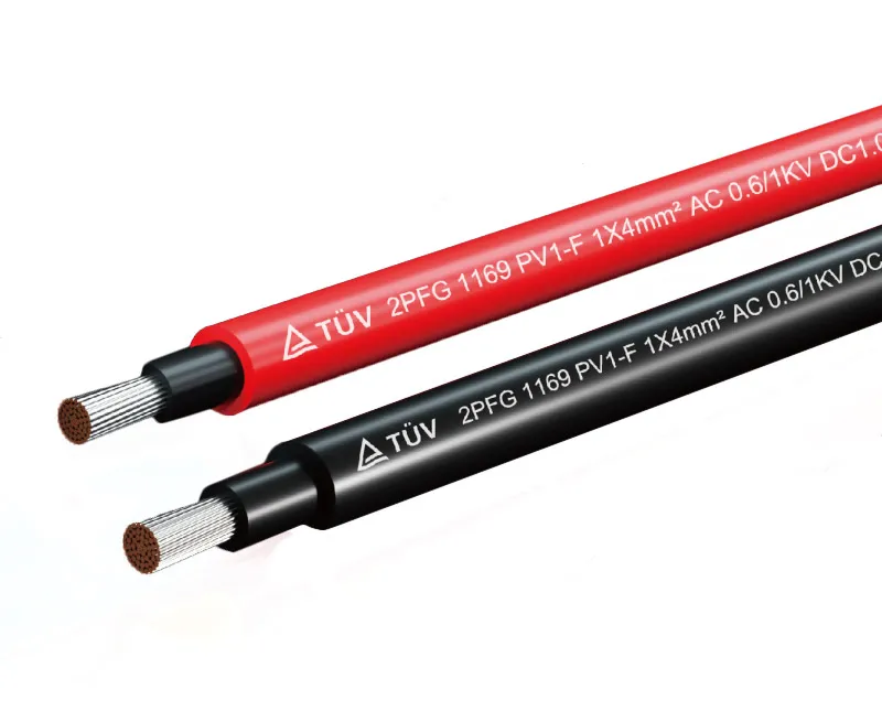
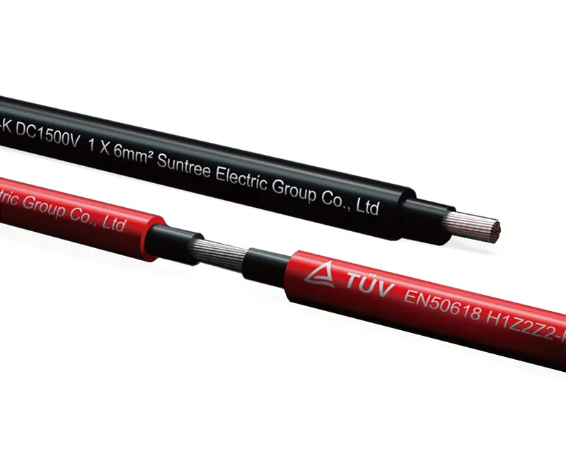
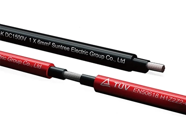
The TUV Single Core Solar Cable EN50618/IEC62930 from Suntree is manufactured to meet both EN 50618 (European) and IEC 62930 (international) photovoltaic cable standards. The cable uses 99.97% oxygen-free tinned copper conductors for corrosion resistance in outdoor environments, with cross-linked polyethylene insulation and UV-stabilized thermoplastic elastomer sheath. It is halogen-free, low-smoke, and flame-retardant to IEC 60332-1.
Key specifications include: voltage rating of 1000V DC (EN50618) with H1Z2Z2-K variants rated for 1500V DC; temperature range -40°C to +90°C continuous; service life ≥25 years. The cable passes 1000-hour xenon arc UV aging with ≤15% property degradation, maintains flexibility at -40°C without cracking, and survives 500-cycle abrasion testing. Available in cross-sections from 1.5mm² to 35mm².
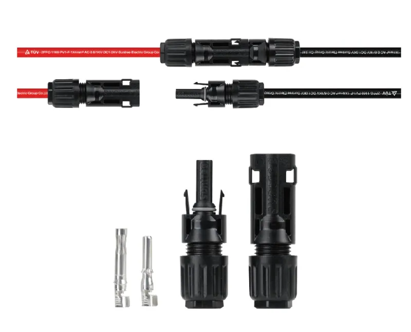
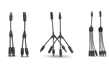
Suntree offers the cable in black and red color coding, standard roll lengths of 100m, 500m, and 1000m, with a 10-year product warranty. The cable is compatible with standard MC4 connectors and crimp terminals.
Making the right choice for commercial projects
A Solar Cable properly sized by the full NEC 690.8 156% calculation, derated for ambient temperature and conduit fill, and checked for voltage drop under 2% DC will pass inspection and deliver rated performance for 25+ years. The cost difference between correct and incorrect sizing appears twice: once in the permit rejection and rework, and again in annual energy loss over the system life. Build the complete calculation into your standard design review process. Keep the 156% rule on a sticky note at every workstation. Voltage drop pays back in kWh that never leave the meter.
→ Request a quote from Suntree for the TUV Single Core Solar Cable EN50618/IEC62930 — Share your target system voltage, string current, and maximum homerun distance. Their technical team can provide ampacity charts and voltage drop calculations for your specific commercial PV installation.
-0943.webp)